Hardware Kit on hand:
- 1 x Nordic nRF5340-DK: PCA10095(2.0.2)
- 1 x AN7002Q-DB-5340-M
- 1 x IDC Ribbon Wire(J-Link Cable)
- 1 x USB Wire–Type C USB
- 1 x USB Wire–Micro USB
Hardware Network:
IDC Ribbon Wire(J-Link Cable): Connect nRF5340-DK to AN7002Q-DB-5340-M
USB Wire–Type C USB: Power supply to AN7002Q-DB-5340-M through USB TYPE-C
USB Wire–Micro USB: Power supply to nRF5340-DK through Micro USB

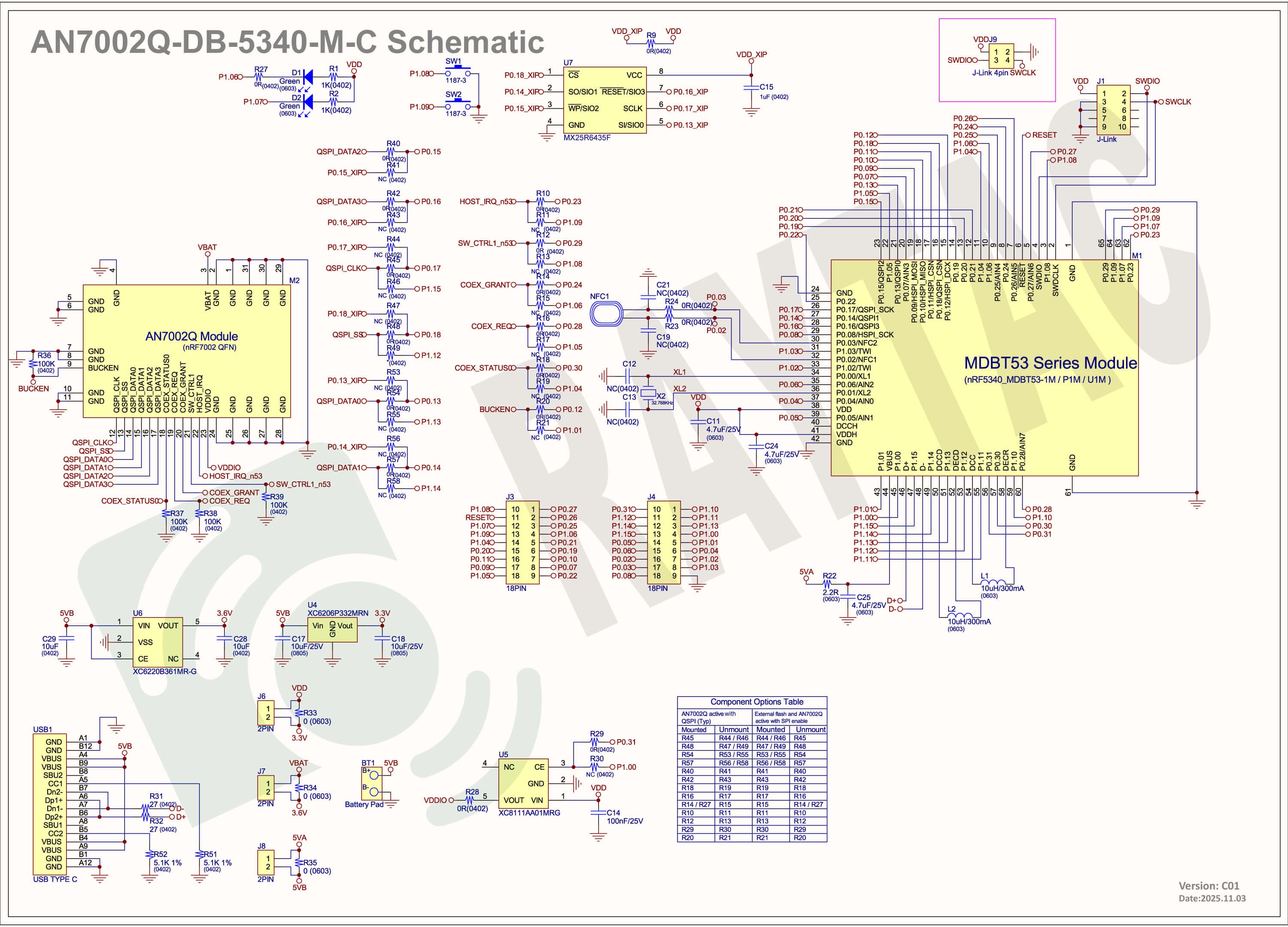
Schematic diagram of AN7002Q-DB-5340-M can be referenced for design as follows.
*nRF7002 module <- SPI -> nRF5340 module
*MX256R NOR Flahs <-QSPI-> nRF7002 module
(Click on the image to zoom in.)
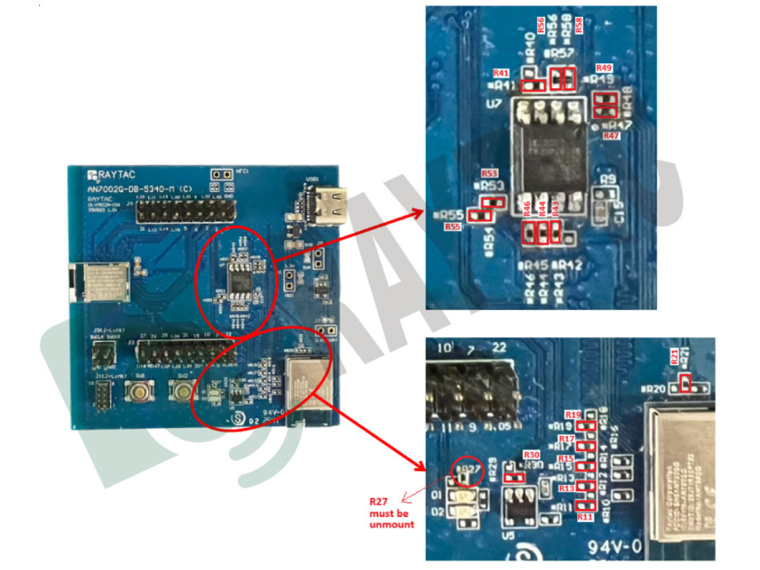
!! Important Note:!!
The circuit of SW1(p1.08)/SW2(p1.09)/LED1(p1.06) on AN7002Q-DB-5340-M is NOT COMPATIBLE to Nordic WI-FI Control Pin of swctrl1(p1.08)/host_irq(p1.09)/grant(p1.06).
In this case, if you’re working with external flash MX25R64 for the WIFI project, Please avoid pin SW1/SW2/LED1 usage while LED2(p1.07) remains available as normal usage.
For the PCB design of end product/end device(mounted with AN7002Q & MDBT53 modules), the switch & LED should be configured to be: SW1(p0.23)/SW2(p0.24)/LED1(p0.28).
2. Software Resources & Preparations
Download nRF Connect For Desktop(Please Click Me)
Download nRF Command Line Tools (Please Click Me)
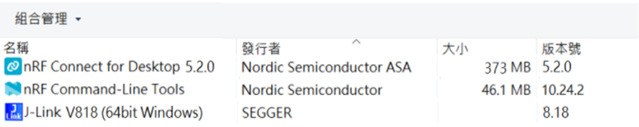
Step 1: Prepared with the latest version of nRF Connect for Desktop, using Windows 64-bit – 5.2.0
Step 2: Prepared with the latest version of Command Line Tools, using Windows X86 64 – 10.24.2
**Note: SEGGER J-LINK Upgrade message might pop up while you’re doing above downloads.
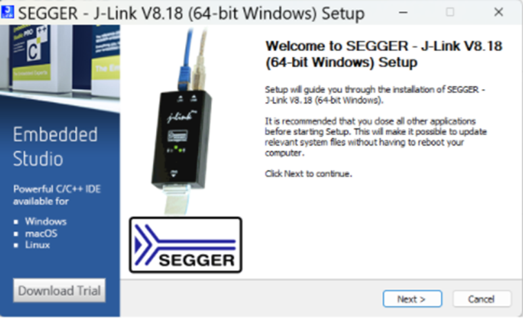
If you’re initiating Segger Embedded Studio (SES) application, please check the guideline here(Click me)
Step 3: Locate all the necessary kits for programming in PC
3. Firmware Build & Compile
After you download and set up nRFConnect SDK (NCS), you will be able to apply free VS (Visual Studio) Code IDE as firmware programming tool.
Here’re the guidelines to developing programs without/with External Flash MX25R64.
A. Project WITHOUT External Flash MX25R64 needed
You can directly build/compile on Nordic NCS without any additional configurations/modifications needed.
B. Project WITH External Flash MX25R64 needed
– Allocate SPI for communication between MDBT53 (BLE) and AN7002Q (WIFI)
– Allocate QSPI for XIP: External flash MX25R64 is activated
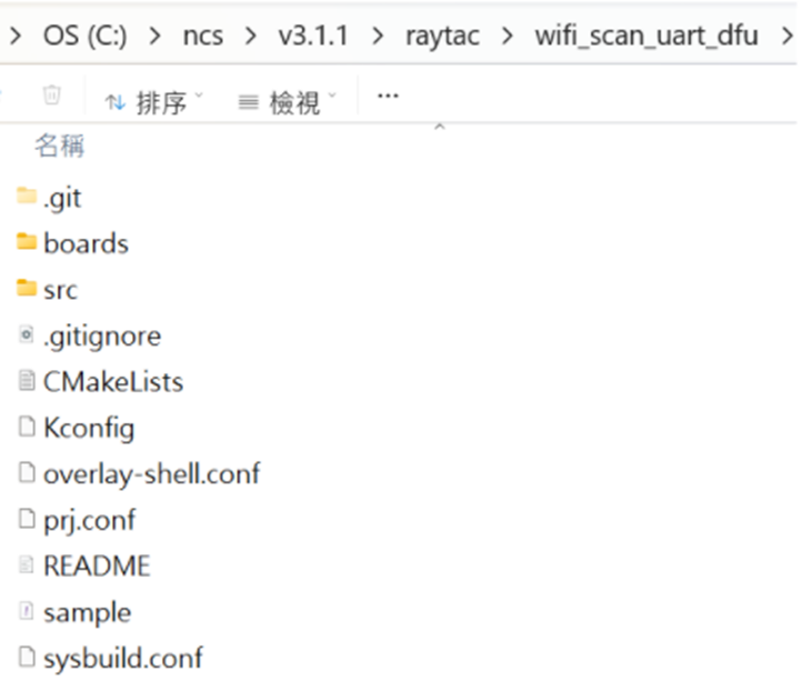
The below example uses NCS v3.1.1 and runs the under: C:\ncs
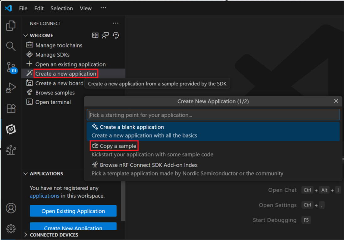
Step 1: Start with a Wi-Fi Scan project and run the program under: C:\ncs\v3.1.1\raytac
<<Create a new application and Copy a sample>>
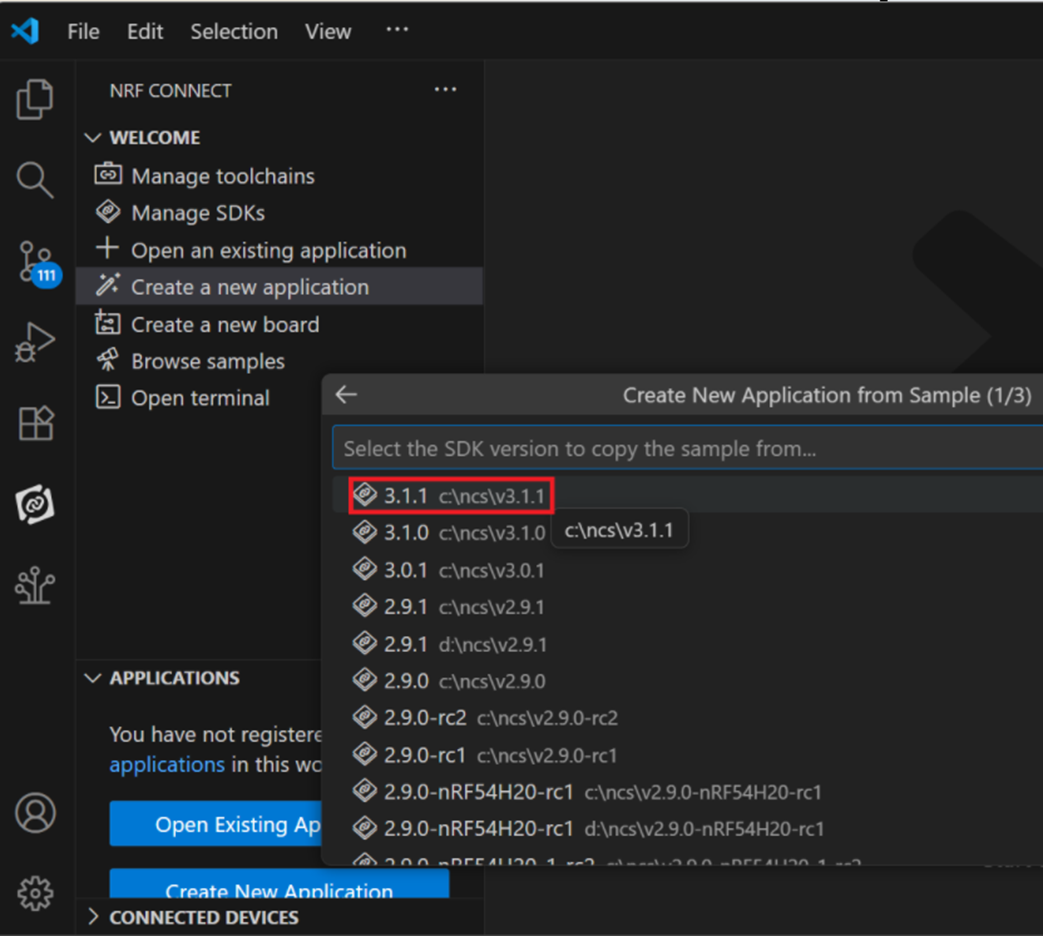
Step 2: Select SDK v3.1.1 to copy the sample
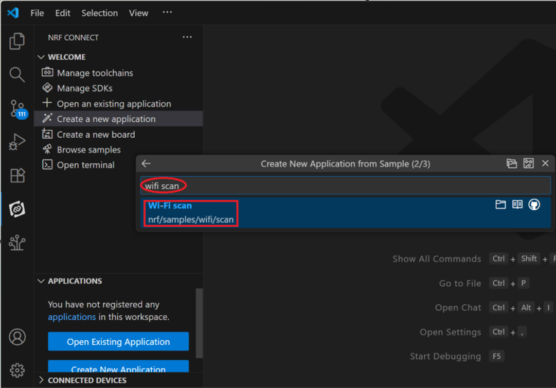
Step 3: Select example by entering keyword: wifi scan(Wi-Fi Scan)
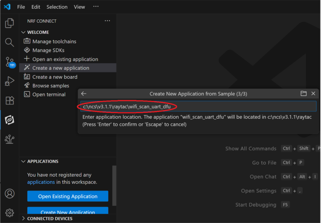
Step 4: Enter application location and name the project as: wifi_scan_uart_dfu
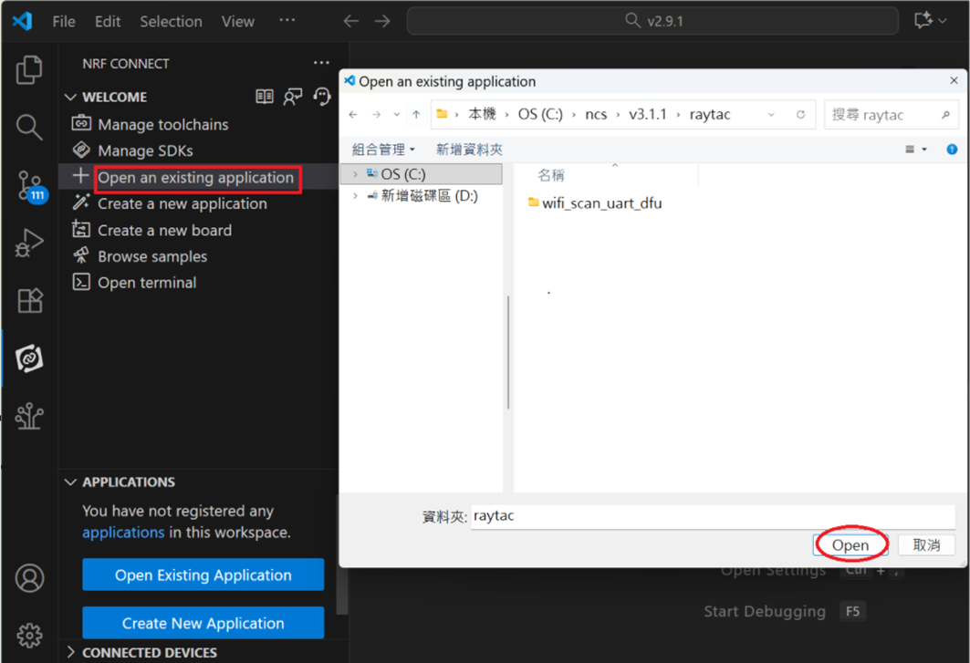
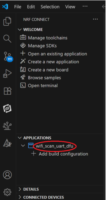
Step 5: Open an existing application and find the registered project: wifi_scan_uart_dfu
Step 6: How to activate the Devicetree setting of Wi-Fi nRF7002 and Create file: nrf5340dk_nrf5340_cpuapp.overlay
Code example is as follows:
/ {
chosen {
aliases {
/delete-node/ leds;
/delete-node/ buttons;
};
};
leds {
compatible = “gpio-leds";
led1: led_1 {
gpios = <&gpio1 7 GPIO_ACTIVE_HIGH>;
label = “Green LED 1″;
};
};
/* These aliases are provided for compatibility with samples */
aliases {
led1 = &led1;
};
};
&mx25r64 {
status = “okay";
};
/ {
chosen {
nordic,pm-ext-flash = &mx25r64;
zephyr,wifi = &wlan0;
};
};
&gpio_fwd {
/delete-node/ uart;
};
&gpio_fwd
{
status = “disabled";
};
&qspi {
status = “okay";
pinctrl-0 = <&qspi_default>;
pinctrl-1 = <&qspi_sleep>;
pinctrl-names = “default", “sleep";
mx25r64: mx25r6435f@0 {
compatible = “nordic,qspi-nor";
reg = <0>;
/* MX25R64 supports only pp and pp4io */
writeoc = “pp4io";
/* MX25R64 supports all readoc options */
readoc = “read4io";
sck-frequency = <8000000>;
jedec-id = [c2 28 17];
sfdp-bfp = [
e5 20 f1 ff ff ff ff 03 44 eb 08 6b 08 3b 04 bb
ee ff ff ff ff ff 00 ff ff ff 00 ff 0c 20 0f 52
10 d8 00 ff 23 72 f5 00 82 ed 04 cc 44 83 68 44
30 b0 30 b0 f7 c4 d5 5c 00 be 29 ff f0 d0 ff ff
];
size = <67108864>;
has-dpd;
t-enter-dpd = <10000>;
t-exit-dpd = <35000>;
};
};
&spi1 {
status = “okay";
compatible = “nordic,nrf-spim";
pinctrl-0 = <&spi1_default>;
pinctrl-1 = <&spi1_sleep>;
pinctrl-names = “default", “sleep";
cs-gpios = <&gpio1 12 GPIO_ACTIVE_LOW >;
nrf70: nrf7002@0 {
status = “okay";
compatible = “nordic,nrf7002-spi";
reg = <0>;
spi-max-frequency = <24000000>;
/* Wi-Fi Pins used */
iovdd-ctrl-gpios = <&gpio1 0 GPIO_ACTIVE_HIGH>;
bucken-gpios = <&gpio1 1 GPIO_ACTIVE_HIGH>;
host-irq-gpios = <&gpio1 9 GPIO_ACTIVE_HIGH>;
wlan0: wlan {
compatible = “nordic,wlan";
};
wifi-max-tx-pwr-2g-dsss = <21>;
wifi-max-tx-pwr-2g-mcs0 = <16>;
wifi-max-tx-pwr-2g-mcs7 = <16>;
wifi-max-tx-pwr-5g-low-mcs0 = <9>;
wifi-max-tx-pwr-5g-low-mcs7 = <9>;
wifi-max-tx-pwr-5g-mid-mcs0 = <11>;
wifi-max-tx-pwr-5g-mid-mcs7 = <11>;
wifi-max-tx-pwr-5g-high-mcs0 = <13>;
wifi-max-tx-pwr-5g-high-mcs7 = <13>;
};
nrf_radio_coex: nrf7002-coex {
status = “okay";
compatible = “nordic,nrf700x-coex";
req-gpios = <&gpio1 5 GPIO_ACTIVE_HIGH>;
status0-gpios = <&gpio1 4 GPIO_ACTIVE_HIGH>;
grant-gpios = <&gpio1 6 (GPIO_PULL_DOWN | GPIO_ACTIVE_LOW)>;
swctrl1-gpios = <&gpio1 8 GPIO_ACTIVE_HIGH>;
};
};
&pinctrl {
spi1_default: spi1_default {
group1 {
psels =
};
};
spi1_sleep: spi1_sleep {
group1 {
psels =
low-power-enable;
};
};
};
/ {
chosen {
zephyr,console = &uart2;
zephyr,shell-uart = &uart2;
};
};
&uart2 {
status = “okay";
current-speed = <115200>;
pinctrl-0 = <&uart2_default>;
pinctrl-1 = <&uart2_sleep>;
pinctrl-names = “default", “sleep";
};
&pinctrl {
uart2_default: uart2_default {
group1 {
psels =
bias-pull-up;
};
};
uart2_sleep: uart2_sleep {
group1 {
psels =
low-power-enable;
};
};
};
Step 7: It is required to do MCUBoot before working with DFU using External Flash
Please do the code configuration in sysbuild.conf as following reference code.
SB_CONFIG_BOOTLOADER_MCUBOOT=y
# DFU with UART
SB_CONFIG_MCUBOOT_MODE_SINGLE_APP=n
# DFU with external flash
SB_CONFIG_PM_EXTERNAL_FLASH_MCUBOOT_SECONDARY=y
Step 8: It is required to do MCUMGR before working with DFU over UART
Please do the code configuration in prj.conf as following reference code.
# Enable QSPI driver for Application
CONFIG_NORDIC_QSPI_NOR=y
# Enable mcumgr DFU in application
CONFIG_MCUMGR=y
CONFIG_NET_BUF=y
CONFIG_ZCBOR=y
CONFIG_CRC=y
# Enable mcumgr management for both OS and Images
CONFIG_MCUMGR_GRP_OS=y
CONFIG_MCUMGR_GRP_IMG=y
CONFIG_FLASH=y
CONFIG_IMG_MANAGER=y
CONFIG_STREAM_FLASH=y
CONFIG_FLASH_MAP=y
# Configure MCUMGR transport to UART
CONFIG_MCUMGR_TRANSPORT_UART=y
CONFIG_BASE64=y
Step 9: Add with MCUBoot setting , and create a root for sysbuild; Build with file mcuboot.overlay & file mcuboot.conf
9A. To the File: mcuboot.overlay
&mx25r64 {
status = “okay";
};
/ {
chosen {
nordic,pm-ext-flash = &mx25r64;
};
};
&gpio_fwd {
/delete-node/ uart;
};
&gpio_fwd
{
status = “disabled";
};
9B. To the File: mcuboot.conf
CONFIG_NORDIC_QSPI_NOR=y
CONFIG_BOOT_MAX_IMG_SECTORS=512
Step 10: Create a VERSION file by referencing the following code when testing DFU over UART.
VERSION_MAJOR = 99
VERSION_MINOR = 0
PATCHLEVEL = 0
VERSION_TWEAK = 0
EXTRAVERSION =
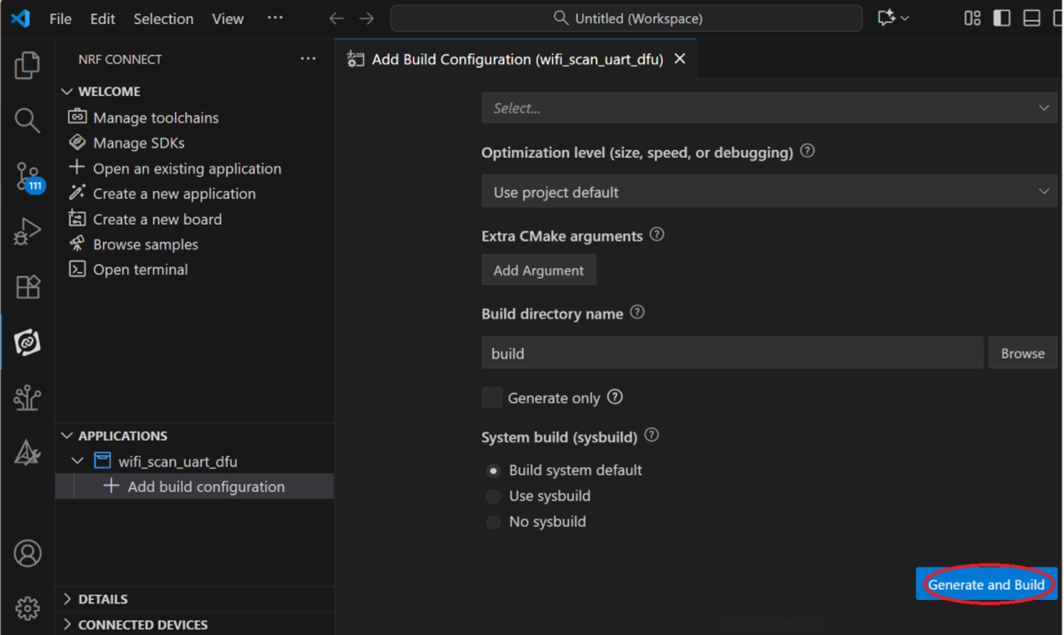
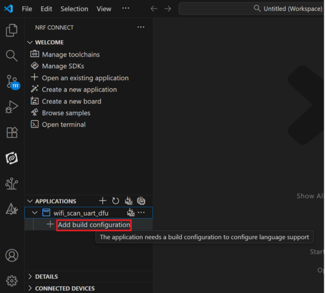
Step 11: Add build configuration.
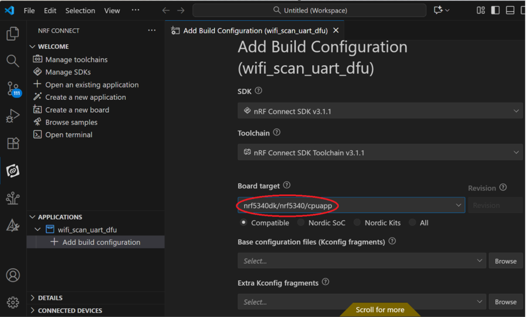
Step 12: Add build configuration >> Choose Board target: nrf5340dk/nrf5340/cpuapp
Step 13: Generate and Build